Heavy-Duty Trucks and Buses
Catalytic Converters – Three-Way Catalytic Converter
The three-way converter (TWC) has been the primary emission control technology on light-duty gasoline vehicles since the early 1980s. The use of TWCs, in conjunction with an oxygen sensor-based, closed-loop fuel delivery system, allows for simultaneous conversion of the three criteria pollutants, HC, CO, and NOx, produced during the combustion of fuel in a spark-ignited engine. The active catalytic materials are present as a thin coating of precious metal (e.g., Pt, Pd, Rh), and oxide-based inorganic promoters and support materials on the internal walls of the honeycomb substrate. The substrate typically provides a large number of parallel flow channels to allow for sufficient contacting area between the exhaust gas and the active catalytic materials without creating excess pressure losses. Although the primary components and function of a TWC has remained relatively constant during its more than twenty years of use on light-duty gasoline vehicles, each of the primary converter components (catalytic coating, substrate, mounting materials) has gone through a continuous evolution and redesign process in order to improve the overall performance of the converter while maintaining a competitive cost effectiveness of the complete assembly.
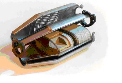
Figure. TWC
Catalytic Converters – Diesel Oxidation Catalyst
In most applications, a diesel oxidation catalyst consists of a stainless steel canister that contains a honeycomb structure called a substrate or catalyst support. There are no moving parts, just large amounts of interior surface area. The interior surfaces are coated with catalytic metals such as platinum or palladium. It is called an oxidation catalyst because the device converts exhaust gas pollutants into harmless gases by means of chemical oxidation. In the case of diesel exhaust, the catalyst oxidizes CO, HCs, and the liquid hydrocarbons adsorbed on carbon particles. In the field of mobile source emission control, liquid hydrocarbons adsorbed on the carbon particles in engine exhaust are referred to as the soluble organic fraction (SOF) — the soluble part of the particulate matter in the exhaust. Diesel oxidation catalysts are efficient at converting the soluble organic fraction of diesel particulate matter into carbon dioxide and water.
Oxidation catalyst retrofits have proven effective at reducing particulate and smoke emissions on older vehicles. Under the U.S. EPA’s urban bus rebuild/retrofit program, five manufacturers certified diesel oxidation catalysts as providing at least a 25 percent reduction in PM emissions for in-use urban buses. Certification data also indicates that oxidation catalysts achieve substantial reductions in CO and HC emissions. Currently, under the ARB and EPA retrofit technology verification processes, several technology manufacturers have verified diesel oxidation catalysts as providing at least a 25 percent reduction in PM emissions.
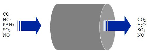
Figure. DOC
Catalytic Converters – SCR System
A Selective Catalytic Reduction (SCR) system uses a metallic or ceramic wash-coated catalyzed substrate, or a homogeneously extruded catalyst and a chemical reductant to convert nitrogen oxides to molecular nitrogen and oxygen in oxygen-rich exhaust streams like those encountered with diesel engines. In mobile source applications, an aqueous urea solution is usually the preferred reductant. Upon thermal decomposition in the exhaust, urea decomposes to ammonia which serves as the reductant. In some cases ammonia has been used as the reductant in mobile source retrofit applications. As exhaust and reductant pass over the SCR catalyst, chemical reactions occur that reduce NOx emissions to nitrogen and water. SCR catalysts can be combined with a particulate filter for combined reductions of both PM and NOx.
Open loop SCR systems can reduce NOx emissions by 75 to 90 percent. Closed loop systems on stationary engines can achieve NOx reductions of greater than 95 percent. SCR systems are also effective in reducing HC emissions up to 80 percent and PM emissions 20 to 30 percent. Like all catalyst-based emission control technologies, SCR performance is enhanced by the use of low sulfur fuel.
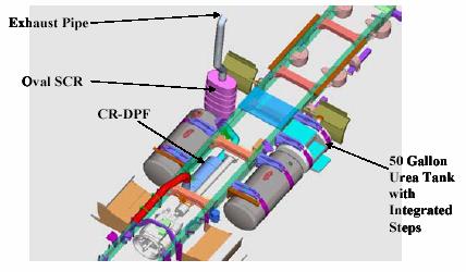
Figure. SCR System
Catalytic Converters – Lean NOx Catalyst
Controlling NOx emissions from a diesel engine is inherently difficult because diesel engines are designed to run lean. In the oxygen-rich environment of diesel exhaust, it is difficult to chemically reduce NOx to molecular nitrogen. The conversion of NOx to molecular nitrogen in the exhaust stream requires a reductant (HC, CO or H2) and under typical engine operating conditions, sufficient quantities of reductant are not present to facilitate the conversion of NOx to nitrogen.
Some lean NOx catalyst (LNC) systems inject a small amount of diesel fuel or other reductant into the exhaust upstream of the catalyst. The fuel or other hydrocarbon reductant serves as a reducing agent for the catalytic conversion of NOx to N2. Other systems operate passively without any added reductant at reduced NOx conversion rates. A lean NOx catalyst often includes a porous material made of zeolite (a micro-porous material with a highly ordered channel structure), along with either a precious metal or base metal catalyst. The zeolites provide microscopic sites that are fuel/hydrocarbon rich where reduction reactions can take place. Without the added fuel and catalyst, reduction reactions that convert NOx to N2 would not take place because of excess oxygen present in the exhaust. Currently, peak NOx conversion efficiencies typically are around 10 to 30 percent (at reasonable levels of diesel fuel reductant consumption).
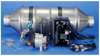
Figure. LNC
Catalytic Converters – Lean NOx Trap
Another type of catalyst being developed for diesel engines are known as lean NOx traps (LNT) because they function by trapping the NOx in the form of a metal nitrate during lean operation of the engine. The most common compound used to capture NOx is Barium Hydroxide or Barium Carbonate. Under lean air to fuel operation, NOx reacts to form NO2 over a platinum catalyst followed by reaction with the Barium compound to form BaNO3. Following a certain amount of lean operation, the trapping function will become saturated and must be regenerated. This is commonly done by operating the engine in a fuel rich mode for a brief period of time to facilitate the conversion of the barium compound back to a hydrated or carbonated form and giving up NOx in the form of N2 or NH3. LNT catalyst can be combined with a zeolite based SCR catalyst to trap ammonia and further reduce NOx via a selective catalytic reduction reaction to nitrogen.
Particulate Filters – Partial or Flow-Through Filter
Diesel particulate filters remove particulate matter found in diesel exhaust by filtering exhaust from the engine. Diesel particulate filters (DPFs) come in a variety of types depending on the level of filtration required. The simplest form of particulate removal can be achieved using a diesel oxidation catalyst (DOC). DPFs can be either partial, flow-through devices or wall-flow designs which achieve the highest filtration efficiency.
Partial or Flow-Through Filters: The first level of filtration can be achieved using a partial or flow-through particulate filter. In this type of device, the filter element can be made up of a variety of materials and designs such as, sintered metal, metal mesh or wire, or a reticulated metal or ceramic foam structure. In this type of device, the exhaust gases and PM follow a tortuous path through a relatively open network. The partial filtration occurs as particles impinge on the rough surface of the mesh or wire network of the filter element. Partial filters can be catalyzed or uncatalyzed and are less prone to plugging than the more commonly used wall-flow filters.
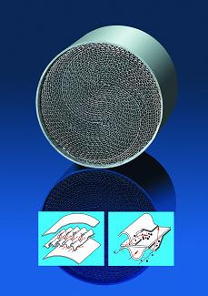
Figure. FTF
Particulate Filters – High-Efficiency Wall-Flow Filter
Diesel particulate filters remove particulate matter found in diesel exhaust by filtering exhaust from the engine. Diesel particulate filters (DPFs) come in a variety of types depending on the level of filtration required. The simplest form of particulate removal can be achieved using a diesel oxidation catalyst (DOC). DPFs can be either partial, flow-through devices or wall-flow designs which achieve the highest filtration efficiency.
High-Efficiency Wall-Flow Filters: In order to meet the stringent particulate emissions that are required for diesel heavy-duty vehicles starting with the 2007 model year, the highest efficiency particulate filter is required. These are commonly made from ceramic materials such as cordierite, aluminum titanate, mullite, or silicon carbide. The basis for the design of wall-flow filters is a honeycomb structure with alternate channels plugged at opposite ends. As the gases pass into the open end of a channel, the plug at the opposite end forces the gases through the porous wall of the honeycomb channel and out through the neighboring channel. The ultrafine porous structure of the channel walls results in greater than 85 percent collection efficiencies of these filters. Wall-flow filters capture particulate matter by interception and impaction of the solid particles across the porous wall. The exhaust gas is allowed to pass through in order to maintain low pressure drop.
Since a filter can fill up over time by developing a layer of retained particles on the inside surface of the porous wall, engineers that design engines and filter systems must provide a means of burning off or removing accumulated particulate matter and thus regenerating the filter. A convenient means of disposing of accumulated particulate matter is to burn or oxidize it on the filter when exhaust temperatures are adequate. By burning off trapped material, the filter is cleaned or “regenerated” to its original state. The frequency of regeneration is determined by the amount of soot build-up resulting in an increase in back pressure. To facilitate decomposition of the soot, a catalyst is used either in the form of a coating on the filter or a catalyst added to the fuel. Filters that regenerate in this so-called “passive” fashion cannot be used in all situations. The experience with catalyzed filters indicates that there is a virtually complete reduction in odor and in the soluble organic fraction of the particulate. Despite the high efficiency of the catalyst, a layer of ash may build up on the filter requiring replacement or servicing. The ash is made up of inorganic oxides from the fuel or lubricants used in the engine and will not decompose during the regular soot regeneration process.
In some applications or operating cycles, the exhaust never achieves a high enough temperature to completely oxidize the soot even in the presence of a catalyst. In these instances, an “active” regeneration system must be employed. Active regeneration utilizes a fuel burner or a resistively heated electric element to heat the filter and oxidize the soot. Active regeneration can be employed either in-place on the vehicle or externally. During external regeneration, the filter is removed from the vehicle and heated in a controlled chamber.
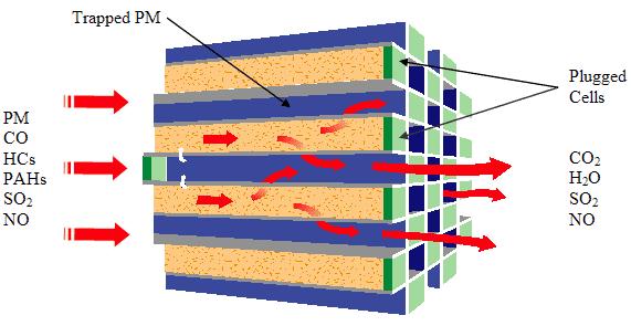
Figure. DPF
Sensor Technologies – Temperature Sensor
Temperature sensors are used for two purposes: The first is as a warning system, typically on obsolete oxidation-only catalytic converters. The function of the sensor is to warn of temperature excursions above the safe operating temperature of the catalytic converter. However, modern catalytic converters are not as susceptible to temperature damage. Many modern three-way Platinum-based converters are able to handle temperatures of 900 degrees C sustained, while many modern three-way Palladium-based converters are able to handle temperatures of 925 degrees C sustained. Temperature sensors are also used to monitor the temperature rise over the catalytic converter core.
Sensor Technologies – Oxygen Sensor
Oxygen sensors are part of the closed loop fuel feedback control system, associated with modern three-way catalyst emission control systems on gasoline engines. The closed loop fuel feedback control system is responsible for controlling the air/fuel ratio of the catalytic converter feed gas. During the closed loop operation, the electronic control module (ECM) keeps the air/fuel ratio adjusted to around the ideal 14.7 to 1 ratio. Signal from the oxygen sensor is used to determine the exact concentration of oxygen in the exhaust stream. From this signal, the ECM determines whether the mixture is richer or leaner than the ideal 14.7 to 1 air/fuel ratio. If the air/fuel ratio deviates from its preprogrammed swings, catalyst efficiency decreases dramatically, especially for NOx reduction. The oxygen sensor informs the ECM of needed adjustments to injector duration based on exhaust conditions. After adjustments are made, the oxygen sensor monitors the correction accuracy and informs the ECM of additional adjustments. The oxygen sensor is also an integral part of the onboard diagnostic (OBD) system which monitors the proper functioning of the emission control system of the vehicle. If the sensor detects oxygen content of the exhaust that is outside the specified range of the engine calibration, it will trigger the engine light to come on in the instrument cluster.
Sensor Technologies – NOx Sensor
NOx sensors represent state of the art technology that can be applied to gasoline lean burn engines as part of a broader engine control or diagnostic system used to insure proper operation of the NOx emission control system. These sensors can be incorporated independent of the NOx emission control technology used on the vehicle and their function is primarily to monitor the NOx conversion efficiency of the catalyst. The sensors can work as part of a feedback loop to the control unit on the emissions system to make real time adjustments and optimize NOx conversion. The principle of operation of one type of NOx sensor is based on proven solid electrolyte technology developed for oxygen sensors. The dual chamber zirconia sensing element and electro-chemical pumps work in conjunction with precious metal catalyst electrodes to control the oxygen concentration within the sensor and convert the NOx to nitrogen. The sensor sends output signals in volts that are directly proportional to ppm NOx concentration. The sensors can be incorporated upstream and downstream of the catalyst, for example, to provide a feedback control loop to the ECU of the emissions system. The ECU can than make adjustments to optimize NOx conversion performance. The ECU can than make adjustments to optimize NOx conversion performance. In the case of SCR technology, feedback can also be provided to the urea dosing system whereas in the case of lean NOx trap technology a feedback loop could signal the regeneration of the trap.
Thermal Management Strategies
The majority of emissions from today’s gasoline and diesel engines occur during cold start before the catalyst can achieve optimum operating temperatures. Exhaust system manufacturers have been working together with catalyst companies to develop ways to heat up the catalyst as quickly as possible. The greatest impact came from the introduction of close coupled catalysts (CCC) to supplement the existing underfloor systems in the mid-1990. This positioned a smaller catalytic converter close to the exhaust manifold to allow rapid oxidation of CO and hydrocarbons. The exothermic heat generated in the CCC by these reactions facilitates the rapid heat up of the down stream, larger, underfloor, TWC. In later developments, the CCC was sometimes formulated to be a fully functional TWC with the underfloor unit serving as a clean-up catalyst to convert the final 10-20% of the pollutants.
The beneficial impact on reducing cold start emissions via thermal management has led to numerous improvements to the exhaust system components up stream of the converter in order to retain as much heat as possible in the exhaust gases. Manufacturers have developed ways to insulate the exhaust manifold and exhaust pipe. Attaching the CCC to a double walled, stainless steel exhaust pipe containing an air gap within the tube walls is probably the most common thermal management strategy used today. To meet the tightest SULEV and PZEV regulations required attention to the temperature distribution at the face of the CCC. This led to new inlet cone designs and modification to the shape of the space in front of the close coupled substrate.
Engine/Fuel Management
Achieving near-zero exhaust emission targets requires a systems approach. Engine manufacturers are focusing on ways to control engine operation to reduce engine out emissions as low as possible and reduce the burden on the catalysts.
Approaches aimed at reducing cold start emissions involve retarding the ignition timing so as to allow some hydrocarbons to pass through in the exhaust and light off the catalyst sooner. Variable valve timing (VVT) is being used to introduce some fraction of exhaust gas into the combustion process and reduce HC and NOx emissions. On clean diesel engines, Exhaust Gas Recirculation (EGR) is used to dilute intake air with some fraction of exhaust gas to lower the combustion temperatures resulting in lower engine out NOx emissions.
Direct injection of fuel into the cylinders rather than port injection has allowed better control of the air fuel ratio during combustion and resulted in better fuel utilization. Improved turbulence and mixing in the intake port of some low emission engines have resulted in a 24% fuel savings. Clean diesel engines have benefited significantly from common rail fuel injection which allows for electronically controlled injection at very high pressures. Through the use of pilot and retarded injection strategies or in combination with injection rate shaping clean diesels have achieved significant reduction in NOx over conventional diesel injection such as pipe-line or unit injection. Common rail and electronic injection control is very effective in carefully controlling post injection of fuel making it suitable for use with emission control devices such as particulate filters, NOx adsorbers and lean NOx catalysts requiring brief periods of fuel rich exhaust to facilitate regeneration of the catalyst or filter.
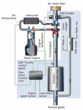
Figure. Low-pressure EGR + DPF
Enhanced Combustion Technologies
Understanding and controlling the combustion process is the first step in reducing engine out emissions and reducing the burden on the emission control systems within the exhaust. Engine design is an important part of controlling and facilitating the combustion process.
In diesel engines, controlling combustion is the key approach to reducing engine out particulate emissions by optimizing the mixing between the fuel and air. Some common ways to increase mixing is through combustion chamber modifications to facilitate turbulent flow as well as fuel injector design to modify the spray pattern. Variable geometry turbocharging (VGT), which delivers variable quantities of pressurized air based on driving conditions, has been effective in reducing PM emissions by maintaining lean combustion in the engine. Reducing compression ratios have been shown effective in reducing combustion temperatures and in turn NOx emissions.
Some common approaches to enhance air turbulence and improve fuel distribution within the cylinders include improvements to the design of fuel injectors, combustion chambers and injection ports. Some engine manufacturers have been able to achieve improvements to the combustion during cold start by making modifications to the design of intake air control valves resulting in a 40-50% reduction in HC emissions and injection ports among others.
Crankcase Emission Controls
Today, in most turbocharged aftercooled diesel engines, the crankcase breather is vented to the atmosphere often using a downward directed draft tube. While a rudimentary filter is often installed on the crankcase breather, substantial amount of particulate matter is released to the atmosphere. Emissions through the breather may exceed 0.7 g/bhp-hr during idle conditions on recent model year engines. For MY 1994 to 2006 heavy-duty diesel engines, crankcase PM emissions reductions provided by crankcase emission control technologies range from 0.01 g/bhp-hr to 0.04 g/bhp-hr or up to 25 percent of the tailpipe emission standards.
One solution to this emissions problem is the use of a multi-stage filter designed to collect, coalesce, and return the emitted lube oil to the engine’s sump. Filtered gases are returned to the intake system, balancing the differential pressures involved. Typical systems consist of a filter housing, a pressure regulator, a pressure relief valve and an oil check valve. These systems greatly reduce crankcase emissions. Crankcase emission controls are available as a retrofit technology for existing diesel engines or as an original equipment component of a new diesel engine.
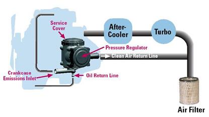
Figure. Crankcase emission control system