Off-Road Spark-Ignited Equipment
Catalytic Converters – Three-Way Catalyst
A three-way catalyst system (TWC) utilizes a precious-metal based catalytic converter, similar in design to the three-way catalytic converters used on cars and trucks, to reduce NOx, unburned HC, and CO. These systems are currently applied to IC engines with fuel-rich ignition systems. For proper operation, the combustion process must occur with an air/fuel ratio slightly fuel-rich of stoichiometry. In the presence of the catalyst under this condition, NOx is reduced by the CO, resulting in nitrogen and carbon dioxide. Typical NOx conversion ranges from 80 to 95 percent with corresponding decreases in CO and HC. In the case of installing retrofit technologies on uncontrolled engines one must also incorporate an engine control unit to achieve the lowest possible emissions. The ECU is normally supplied by the retrofit device manufacturer.
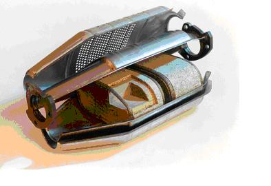
Figure. TWC
Catalytic Converters – Non-Selective Catalytic Reduction System
A non-selective catalytic reduction system (NSCR) utilizes a precious-metal based catalytic converter, similar in design to the three-way catalytic converters used on cars and trucks, to reduce NOx, unburned HC, and CO. NSCR systems are currently applied to IC engines with fuel-rich ignition systems. For proper operation of a NSCR system, the combustion process must occur with an air/fuel ratio slightly fuel-rich of stoichiometry. In the presence of the catalyst under this condition, NOx is reduced by the CO, resulting in nitrogen and carbon dioxide. Typical NOx conversion ranges from 80 to 95 percent with corresponding decreases in CO and HC.
Sensor Technologies – Temperature Sensor
Temperature sensors are used for two purposes: The first is as a warning system, typically on obsolete oxidation-only catalytic converters. The function of the sensor is to warn of temperature excursions above the safe operating temperature of the catalytic converter. However, modern catalytic converters are not as susceptible to temperature damage. Many modern three-way Platinum-based converters are able to handle temperatures of 900 degrees C sustained, while many modern three-way Palladium-based converters are able to handle temperatures of 925 degrees C sustained. Temperature sensors are also used to monitor the temperature rise over the catalytic converter core.
Sensor Technologies – Oxygen Sensor
Oxygen sensors are part of the closed loop fuel feedback control system, associated with modern three-way catalyst emission control systems on gasoline engines. The closed loop fuel feedback control system is responsible for controlling the air/fuel ratio of the catalytic converter feed gas. During the closed loop operation, the electronic control module (ECM) keeps the air/fuel ratio adjusted to around the ideal 14.7 to 1 ratio. Signal from the oxygen sensor is used to determine the exact concentration of oxygen in the exhaust stream. From this signal, the ECM determines whether the mixture is richer or leaner than the ideal 14.7 to 1 air/fuel ratio. If the air/fuel ratio deviates from its preprogrammed swings, catalyst efficiency decreases dramatically, especially for NOx reduction. The oxygen sensor informs the ECM of needed adjustments to injector duration based on exhaust conditions. After adjustments are made, the oxygen sensor monitors the correction accuracy and informs the ECM of additional adjustments. The oxygen sensor is also an integral part of the onboard diagnostic (OBD) system which monitors the proper functioning of the emission control system of the vehicle. If the sensor detects oxygen content of the exhaust that is outside the specified range of the engine calibration, it will trigger the engine light to come on in the instrument cluster.
Thermal Management Strategies
The majority of emissions from today’s gasoline and diesel engines occur during cold start before the catalyst can achieve optimum operating temperatures. Exhaust system manufacturers have been working together with catalyst companies to develop ways to heat up the catalyst as quickly as possible. The greatest impact came from the introduction of close coupled catalysts (CCC) to supplement the existing underfloor systems in the mid-1990. This positioned a smaller catalytic converter close to the exhaust manifold to allow rapid oxidation of CO and hydrocarbons. The exothermic heat generated in the CCC by these reactions facilitates the rapid heat up of the down stream, larger, underfloor, TWC. In later developments, the CCC was sometimes formulated to be a fully functional TWC with the underfloor unit serving as a clean-up catalyst to convert the final 10-20% of the pollutants.
The beneficial impact on reducing cold start emissions via thermal management has led to numerous improvements to the exhaust system components up stream of the converter in order to retain as much heat as possible in the exhaust gases. Manufacturers have developed ways to insulate the exhaust manifold and exhaust pipe. Attaching the CCC to a double walled, stainless steel exhaust pipe containing an air gap within the tube walls is probably the most common thermal management strategy used today. To meet the tightest SULEV and PZEV regulations required attention to the temperature distribution at the face of the CCC. This led to new inlet cone designs and modification to the shape of the space in front of the close coupled substrate.
Engine/Fuel Management
Achieving near-zero exhaust emission targets requires a systems approach. Engine manufacturers are focusing on ways to control engine operation to reduce engine out emissions as low as possible and reduce the burden on the catalysts.
Approaches aimed at reducing cold start emissions involve retarding the ignition timing so as to allow some hydrocarbons to pass through in the exhaust and light off the catalyst sooner. Variable valve timing (VVT) is being used to introduce some fraction of exhaust gas into the combustion process and reduce HC and NOx emissions. On clean diesel engines, Exhaust Gas Recirculation (EGR) is used to dilute intake air with some fraction of exhaust gas to lower the combustion temperatures resulting in lower engine out NOx emissions.
Direct injection of fuel into the cylinders rather than port injection has allowed better control of the air fuel ratio during combustion and resulted in better fuel utilization. Improved turbulence and mixing in the intake port of some low emission engines have resulted in a 24% fuel savings.
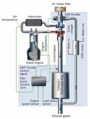
Figure. Low-pressure EGR + DPF
Evaporative Emission Controls
The purpose of evaporative emissions systems is to reduce or eliminate the release of vaporized HC into the atmosphere. The HC vapors, such as volatile organic compounds (VOCs), react in the atmosphere with nitrogen oxides (NOx) and contribute to the formation of ground level ozone and photochemical smog. Ground-level ozone is an air pollutant with harmful effects to plants, human respiratory systems, and an irritant to our eyes.
The major source of evaporative emissions is from the fuel system and, therefore, it is not surprising that fuel injection technology provides significant evaporative emissions benefits. The second major source of evaporative emissions comes from the positive crankcase ventilation (PCV) system. PCV systems collect and consume fuel that is pushed by the piston rings during the compression and power strokes in a 4-stroke (4-cycle) engine. These systems have been used on automobiles since the 1960s in the form of PCV valves. Evaporative emissions regulations have been in effect for automobiles since 1970 in California. Fuel injection systems effectively eliminated the vaporization of fuel from open carburetors. Evaporative emission control systems on cars have increased in complexity over the years to achieve the extremely low evaporative emissions (0.054g/day) from the fuel system as required by California’s Partial Zero Emission Vehicle (PZEV) “zero” evaporative emission limits. Other significant sources of evaporative emissions from the fuel system include permeation of the fuel tank and fuel delivery hoses.
Types of evaporative emissions are classified into five categories:
- Diurnal: This represents gasoline that evaporates due to the rise in ambient temperature.
- Running losses: Represent gasoline that vaporizes due to the heat of the engine and exhaust system during normal operation.
- Resting losses: Natural permeation that occurs from the fuel delivery system while not operating under ambient conditions.
- Hot Soak: Vaporization of fuel due to the retained heat of the engine after the engine is turned off.
- Refueling: Represents the fuel vapors that escape from the tank by the displacement of liquid fuel.
Evaporative emissions are measured using a sealed housing for evaporative determination (SHED) apparatus over the course of a multi-day Federal Test Procedure (FTP) to quantify all of the various forms of evaporative emissions. This testing is generally most effective in determining diurnal and hot soak emissions.
In addition to low permeation hoses, fuel tanks, and seals, evaporative emission controls consists of carbon canisters connected to the fuel system to capture and recycle HC vapors back to the intake of the engine to be consumed as fuel. The carbon is a high-surface area, pelletized material that adsorbs fuel vapors via loose chemical bonds and releases them in a controlled fashion via a purge solenoid. The purge solenoid is activated by the on-board control module when the engine’s control system is operating in “closed” loop fuel control. Carbon materials or other materials that adsorb vapor phase hydrocarbons such as zeolites can also be displayed in the engine’s air intake system to control evaporative emissions associated with fuel leakage from fuel injectors when the engine is not running (see Figure below).
Metal fuel tanks exhibit no permeation; however, the need for lighter weight and complex shapes has led to the development of low permeation plastic tanks. In this case, gas tanks are made of layered polymers and blends that reduce tank permeation by 95% compared to traditional plastic fuel tanks. Similar types of thermo-polymers are molded as thin (0.1 mm) layers in the inside of fuel lines to achieve similar fuel permeation reductions. A vented fuel cap serves to allow air to enter as fuel is depleted while venting expanded vapors in the fuel tank into the carbon canister.
The combination of carbon canisters, the use of low permeable polymers, and fuel injection systems has been demonstrated as a very effective evaporative emissions control strategy. Regulatory agencies around the world are continuing to apply evaporative emission limits to a broad range of on-road and off-road vehicles and engines including motorcycles, small garden equipment, and marine applications.
In the figure below, carbon canisters come in many shapes and sizes, from advanced multi-stage PZEV units (A), to canisters designed for marine (B), to motorcycle and small engine applications (C). (D) is an integrated device to be added to a LEV II evap system/canister vent port to make it a PZEV evap system/canister.
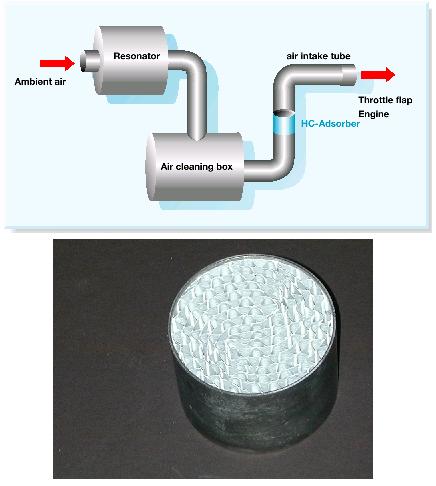
Figure. Air intake hydrocarbon adsorber coated on metal monolith and incorporated into air intake system
Enhanced Combustion Technologies
Understanding and controlling the combustion process is the first step in reducing engine out emissions and reducing the burden on the emission control systems within the exhaust. Engine design is an important part of controlling and facilitating the combustion process.
The most dramatic approach that has been used in recent years on spark-ignited engines is the development of gasoline direct injection (GDI) engines. Early fuel injected engines used a port injection approach where fuel was injected into a port to allow it to evaporate and mix uniformly with the air. This provides little control over the air and fuel mixture entering the cylinder. GDI engines inject the fuel directly into the combustion chamber allowing varying injection strategies depending on engine load. At high load, fuel is injected into the engine early during the induction stroke giving a stoichiometric or rich air/fuel ratio. A GDI engine can also operate in an ultra lean combustion mode during cruising situations when little acceleration is required. In this case the fuel is injected in the latter stages of the compression stroke just prior to ignition. This allows a small amount of fuel to be placed near the spark plug. The effective air fuel ratio is very lean resulting in significant fuel savings. The reason that partial lean burn GDI engines have not reached broad application in the market is the difficulty in meeting NOx emissions regulation during long periods of lean operation. GDI engines can also be designed for stoichiometric operation and make use of three-way catalysts for lowering exhaust emissions.
Some common approaches to enhance air turbulence and improve fuel distribution within the cylinders include improvements to the design of fuel injectors, combustion chambers and injection ports. Some engine manufacturers have been able to achieve improvements to the combustion during cold start by making modifications to the design of intake air control valves resulting in a 40-50% reduction in HC emissions and injection ports among others.